From Arduino to SAP Cloud Platform Internet of Things Service
Introduction
After having heard a lot around Internet of Things (IoT), I wanted to have a better understanding on the end to end process behind such a project and I love the idea of building a small device from which we can get data or even interact with.
Since IoT is not really new anymore, you might have already found a lot of information on the net already. So why yet another blog post? Because I couldn’t find a blog yet that was covering everything from beginning to end…
What I suggest is thus to achieve a very simple project covering the assembling of a devices using an Arduino board, capturing temperature data using a sensor, sending the data to the SAP Cloud Platform IoT Service and publish them through a mean that can be consumed from a device such as a mobile device.
The last bit that we will still miss is the development of an app that will consume the data from the SAP Cloud Platform which could be considered as a follow up to this tutorial.
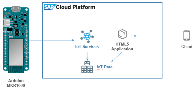
Architecture description

The illustration above shows the complete flow of information from the Arduino board to the data consumer which could be a mobile device. The data collected on the platform are also consumed by an HTML5 Application. There is many possibilities to consumed the data once on the SAP Cloud Platform this diagram represent a solution among many others.
The scope of this tutorial goes beyond the board explaining how to connect a sensor to it and to develop the “Thing”. This tutorial doesn’t go all the way down to the implementation of an application to consume the collected data, we will stop once the data get into the SAP Cloud Platform.
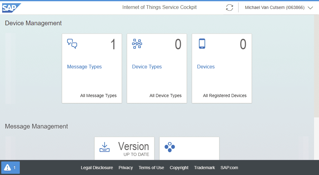
SAP Cloud Platform IoT Service Configuration
Enabling and accessing the SCP IoT Service
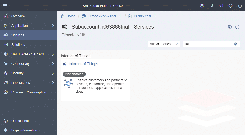
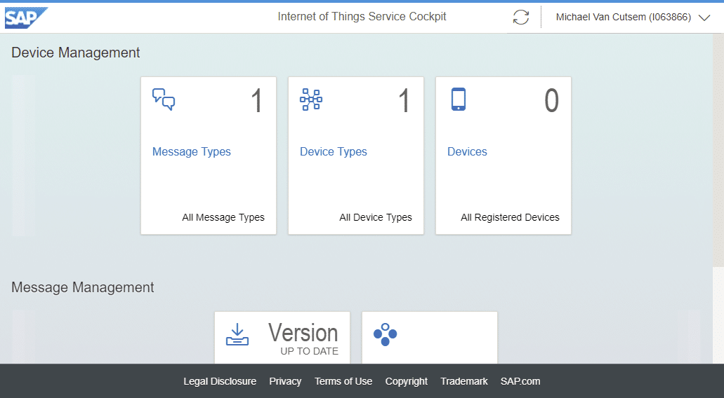
In your SAP Cloud Platform (SCP) go to the Services section and enter “iot” in the filter to display directly the “Internet of Things” service.
If the service has not been enable yet go into the service and press the Enable button.
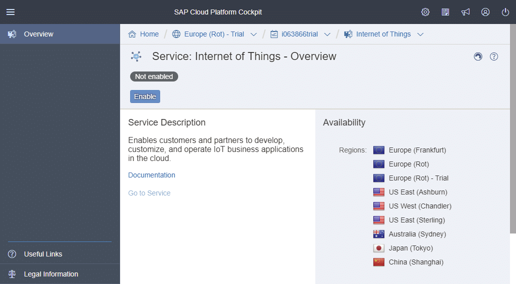
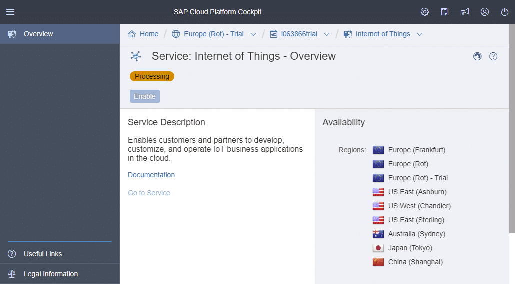
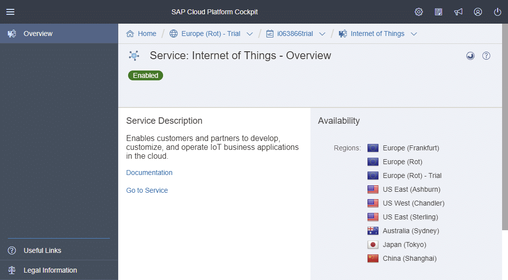
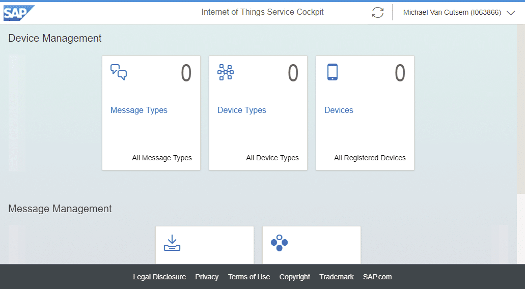
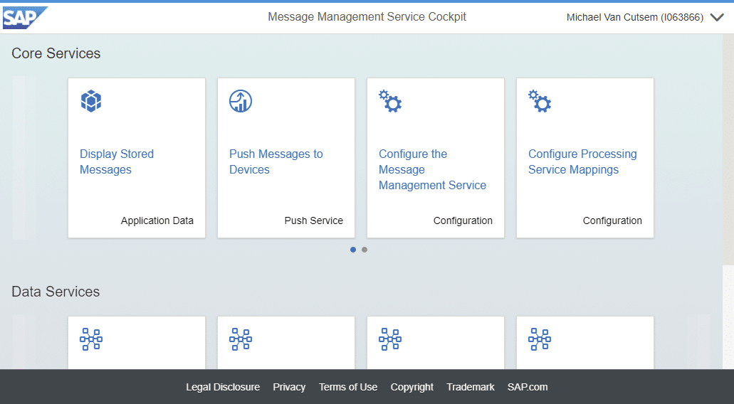
Once the service enabled you can click on the link “Go to Service”.

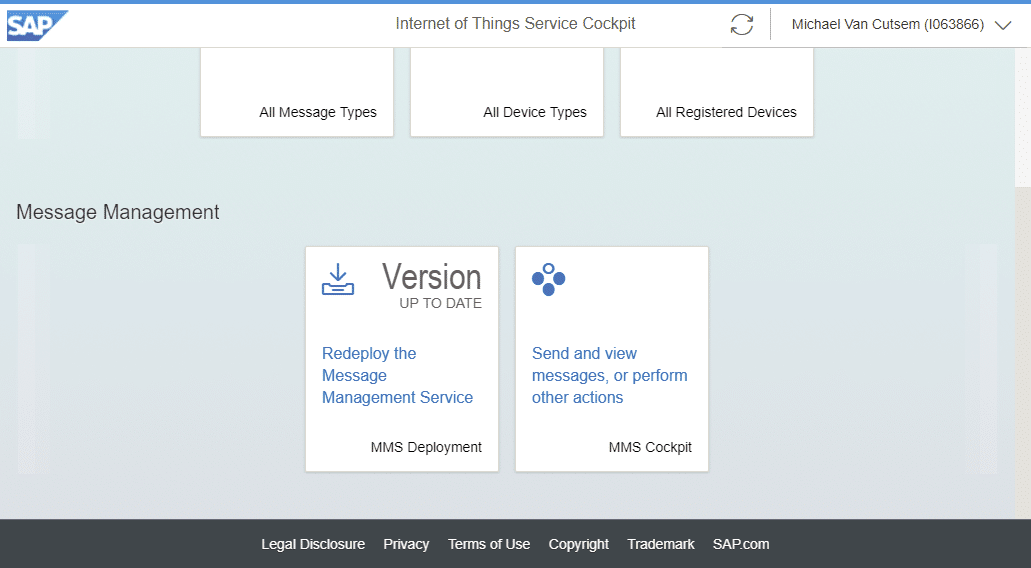
Deploying the Message and Management Service (MMS)
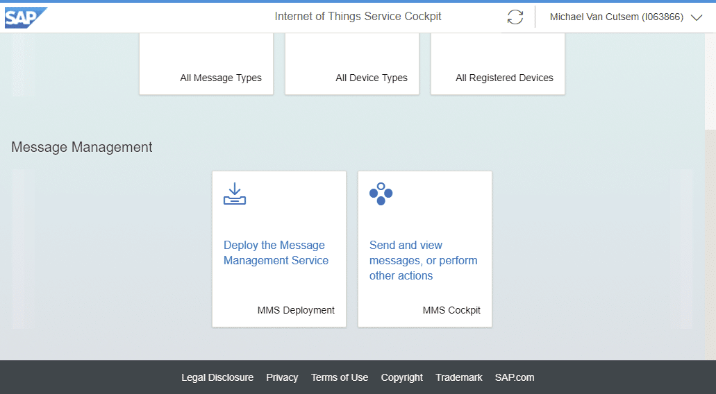
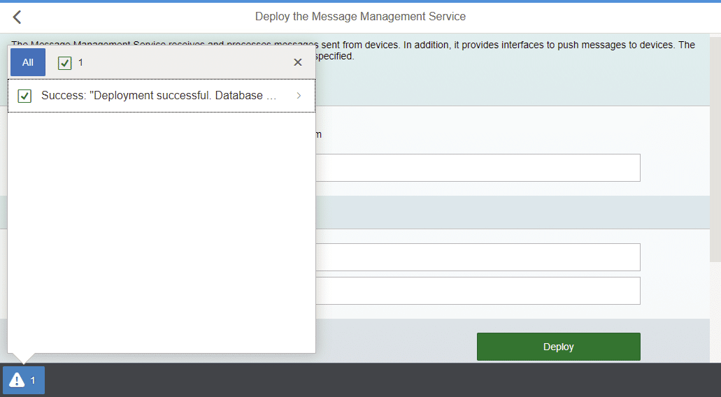
In the IoT service, go to the bottom of the page and click on the tile “Deploy the Message Management Service”.
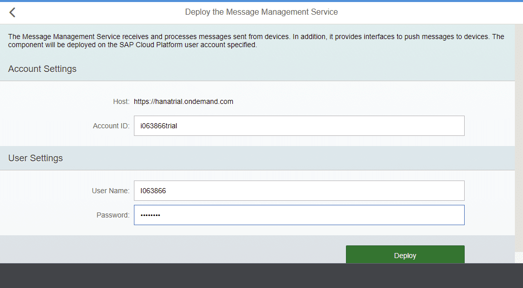
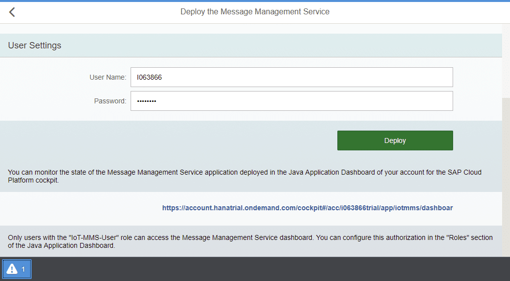
Provide your Account ID and your credentials for the Platform.
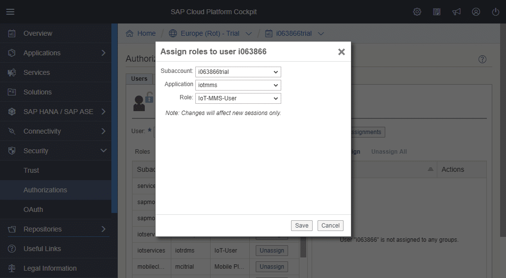
Granting IoT-MMS-User role
As mentioned in the interface: “Only users with the “IoT-MMS-User” role can access the Message Management Service dashboard. You can configure this authorization in the “Roles” section of the Java Application Dashboard.” The next step is therefore to add that role to your user.
In SCP, go to the Security ► Authorizations.
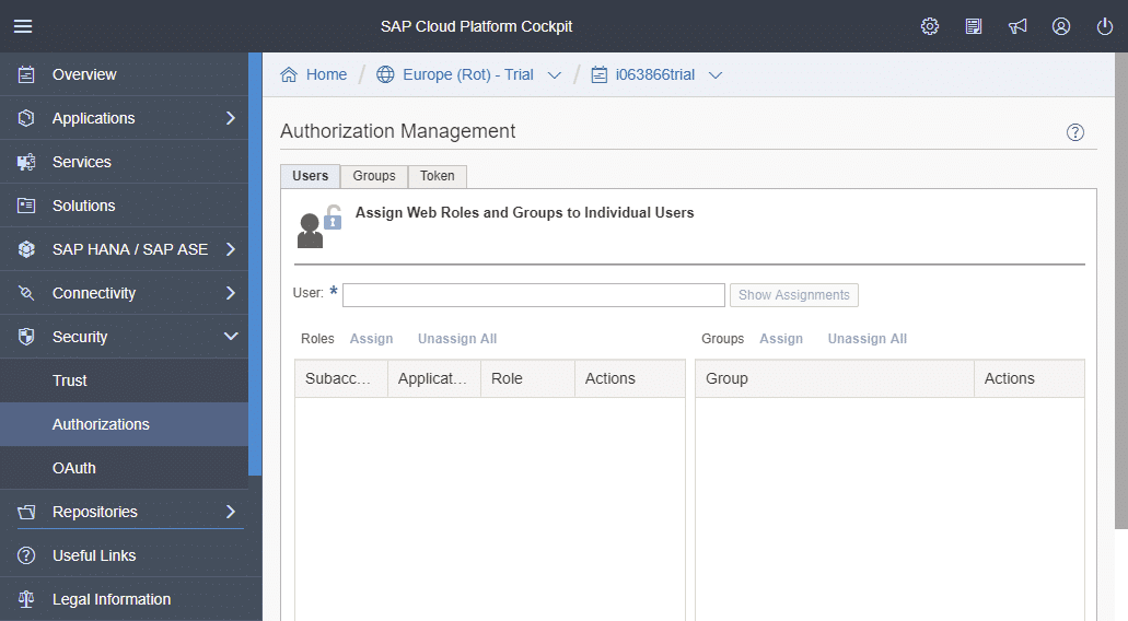
In the “User” tab, enter your user id and press “Show Assignments”.
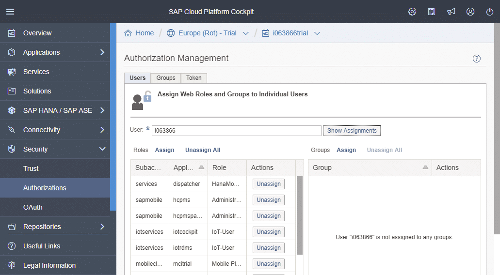
Click on the “Assign” link above the table. Select the “iotmms” Application and the “IoT-MMS-User” Role. Press the “Save” button.
We have now successfully configured the Platform to benefit from the IoT service and our user is capable to access it and work with it.
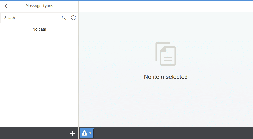
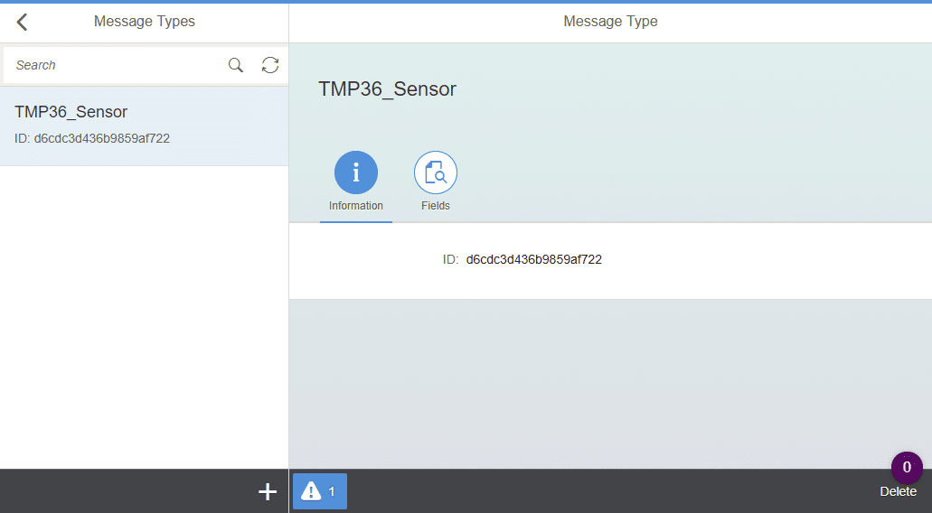
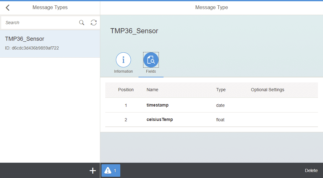
Defining a message type
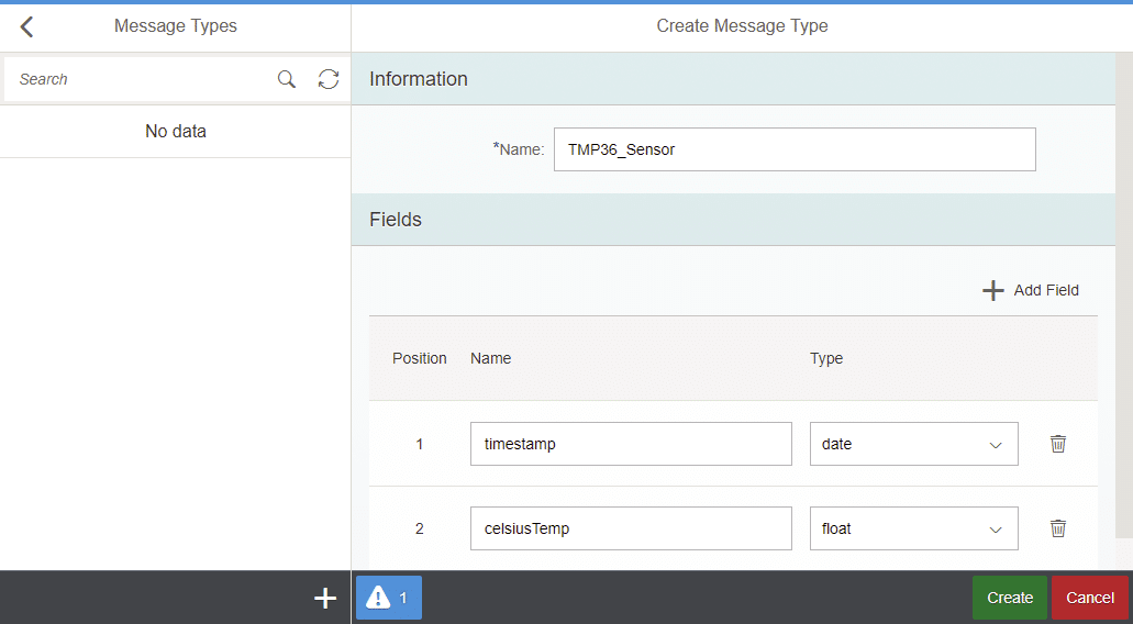
NOTE: the timestamp that is sent should be an epoch date/time. SCP will apply the time zone adjustment itself. You send 23:30 epoch and 00:30 will be shown as data in IoT service…
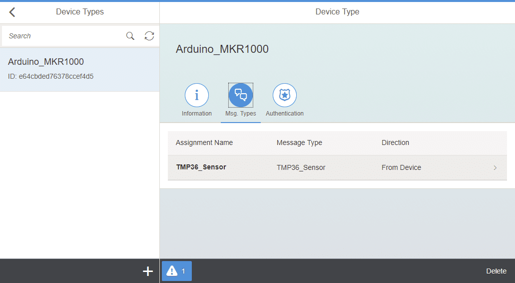
Creating a device type
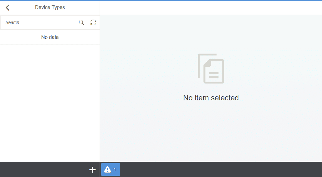
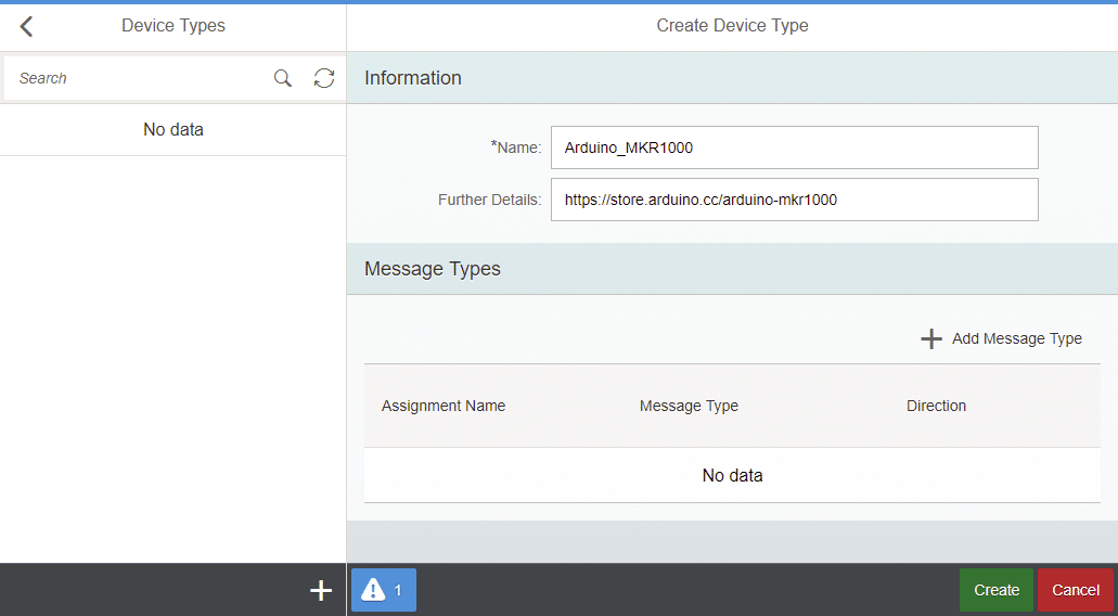
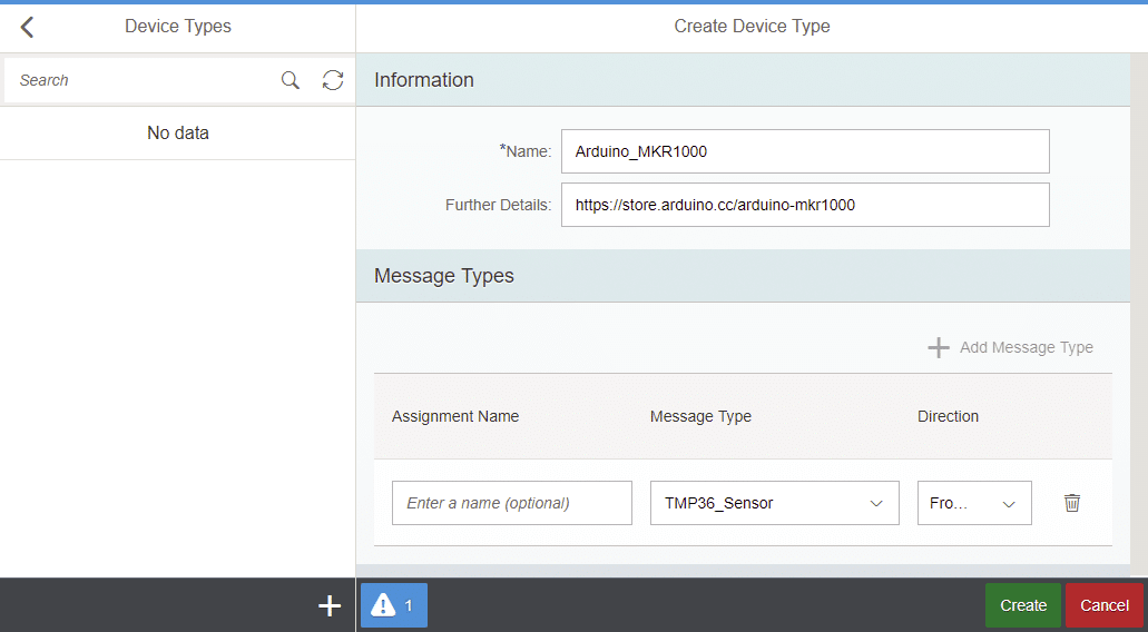
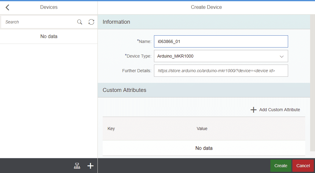
Press the “Create” button.
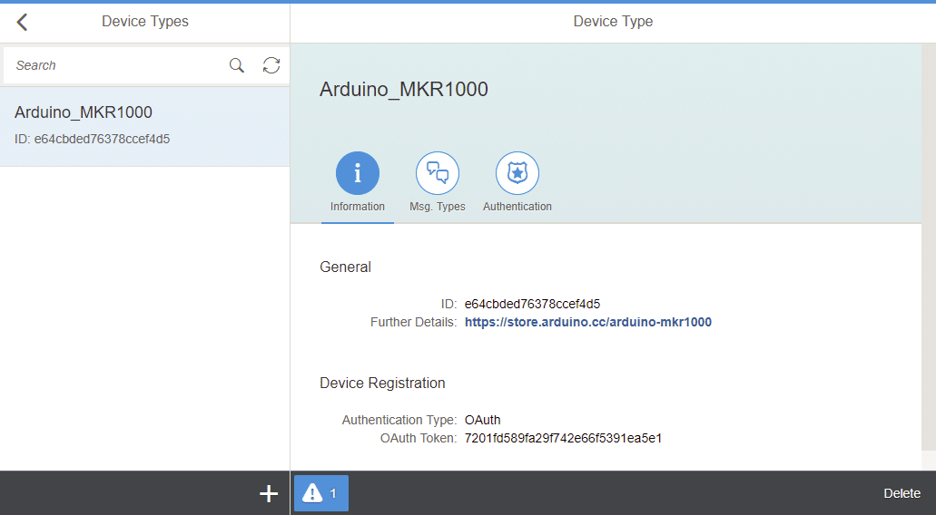
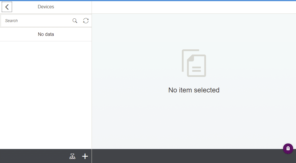
Adding a device
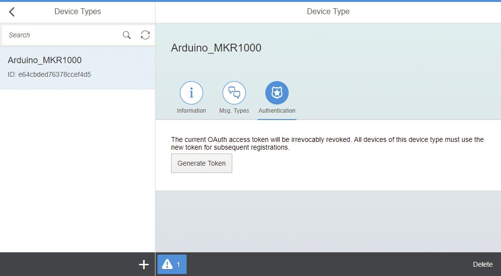
Some “sensible” data such as the security token and devices IDs are handled in this section. Most people would scramble everything, I don’t. I prefer to have something pretty transparent and clear. The project described in this tutorial as already moved to another level and almost everything of what have been described in this blog doesn’t even exist anymore.
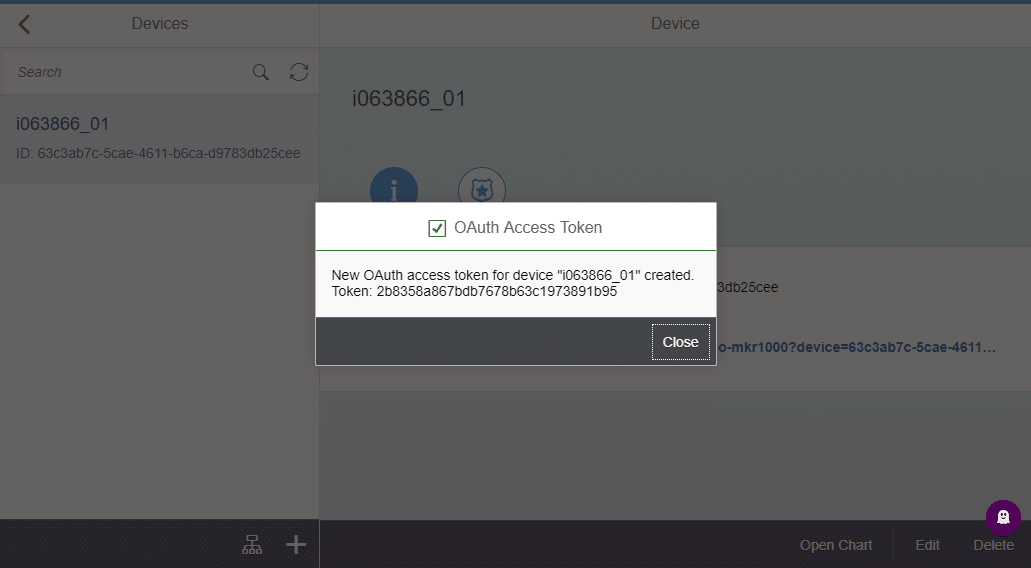
New OAuth access token for device “i063866_01” created. Token: 2b8358a867bdb7678b63c1973891b95
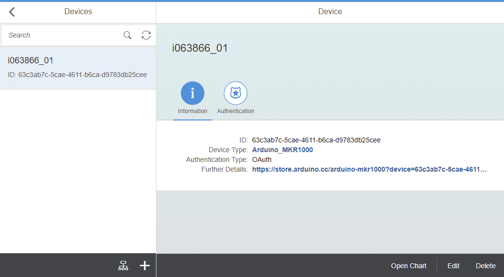
Device ID: 63c3ab7c-5cae-4611-b6ca-d9783db25cee
OAuth Token: 2b8358a867bdb7678b63c1973891b95
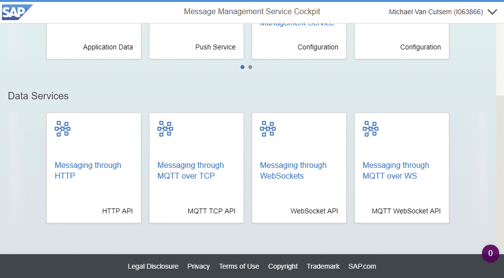
Testing/Sending information from and to the MMS


Scroll down and click on the tile “Messaging through HTTP”.
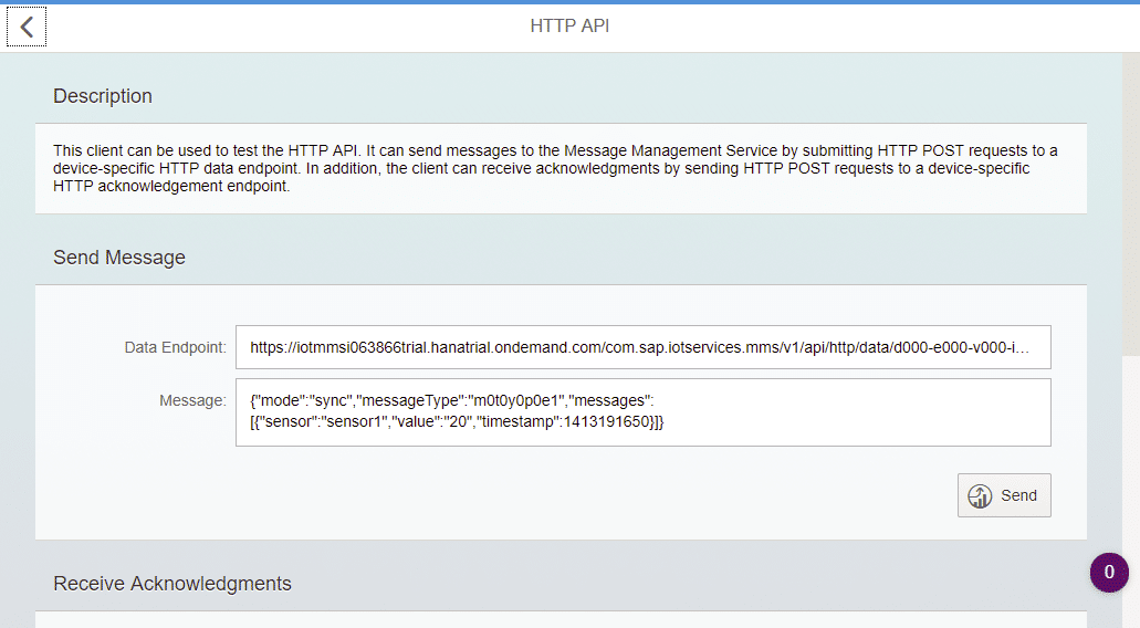
Data Endpoint: https://iotmmsi063866trial.hanatrial.ondemand.com/com.sap.iotservices.mms/v1/api/http/data/d000-e000-v000-i000-c000-e001
Message: {“mode”:”sync”,”messageType”:”m0t0y0p0e1″,”messages”:[{“sensor”:”sensor1″,”value”:”20″,”timestamp”:1413191650}]}
Modify the following info from the template (Data Endpoint and Message):
- d000-e000-v000-i000-c000-e001 ► Device ID [63c3ab7c-5cae-4611-b6ca-d9783db25cee]
- m0t0y0p0e1 ► Message Type ID [d6cdc3d436b9859af722]
- {“sensor”:”sensor1″,”value”:”20″,”timestamp”:1413191650} ► {“timestamp”:1413191650,”celsiusTemp”:”25.8″}
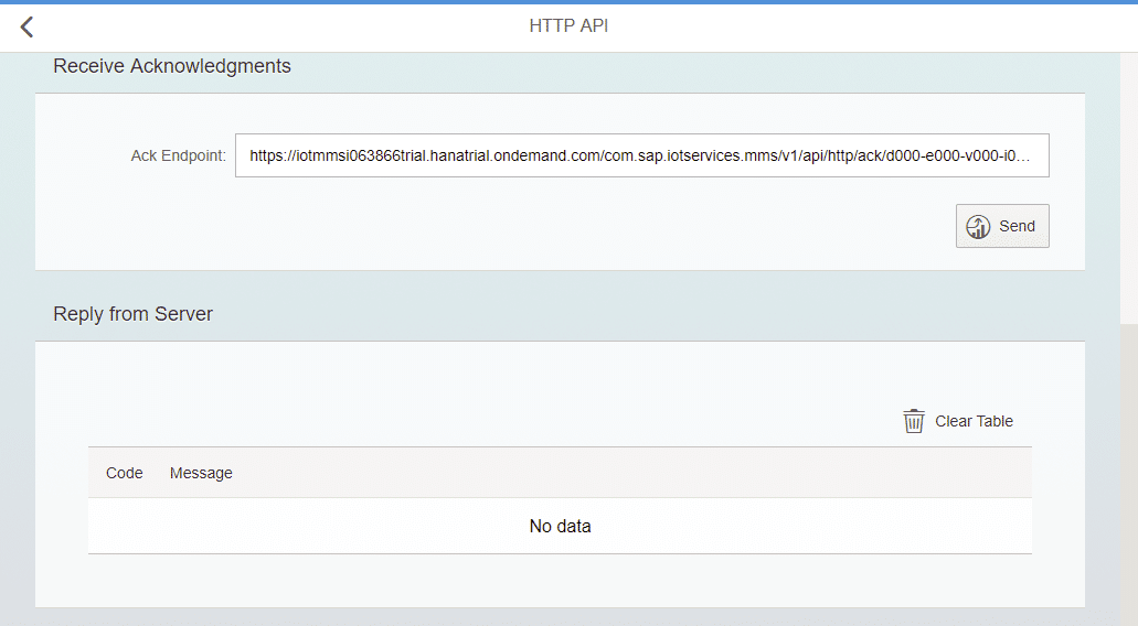
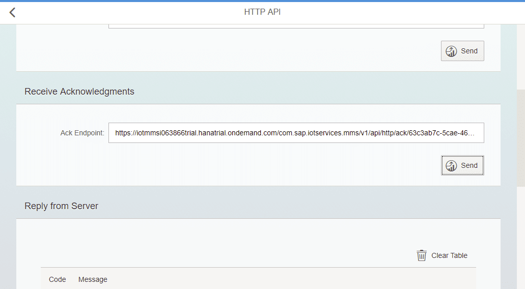
Ack Endpoint: https://iotmmsi063866trial.hanatrial.ondemand.com/com.sap.iotservices.mms/v1/api/http/ack/d000-e000-v000-i000-c000-e001
Modify the following info from the Ack Endpoint template:
- d000-e000-v000-i000-c000-e001 ► Device ID [63c3ab7c-5cae-4611-b6ca-d9783db25cee]
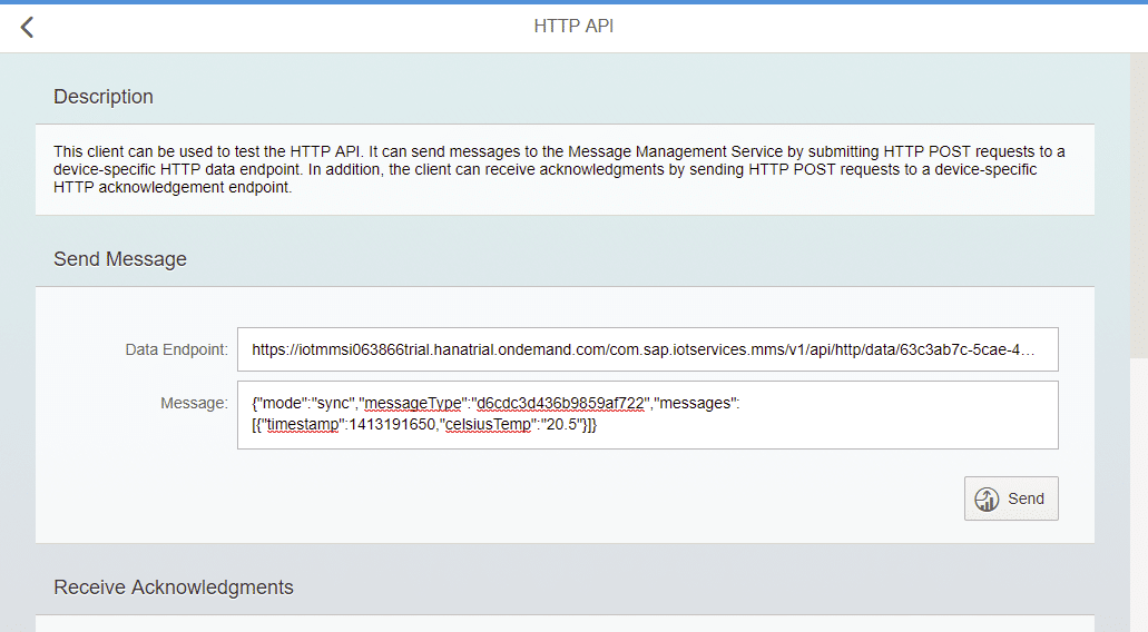
Summary of the key information
- Data Endpoint: https://iotmmsi063866trial.hanatrial.ondemand.com/com.sap.iotservices.mms/v1/api/http/data/63c3ab7c-5cae-4611-b6ca-d9783db25cee
- Message: {“mode”:”sync”,”messageType”:”d6cdc3d436b9859af722“,”messages”:[{“timestamp”:1413191650,”celsiusTemp”:”20″}]}
- Ack Endpoint: https://iotmmsi063866trial.hanatrial.ondemand.com/com.sap.iotservices.mms/v1/api/http/ack/63c3ab7c-5cae-4611-b6ca-d9783db25cee
Running the test
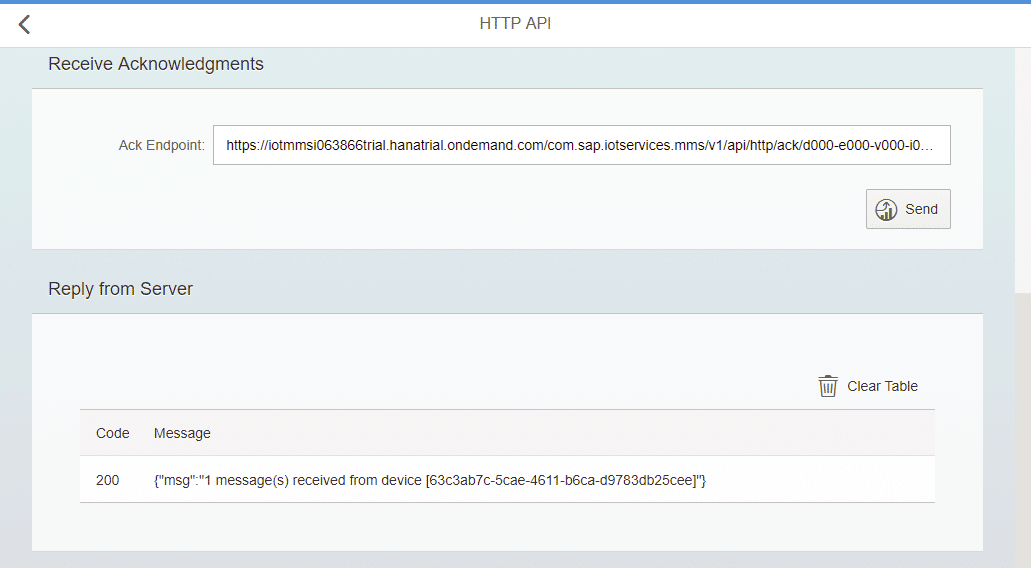
The very first time this request succeed you might get a 202 (The request has been accepted for processing, but the processing has not been completed). Then the following ones will be a 200 (The request has succeeded).
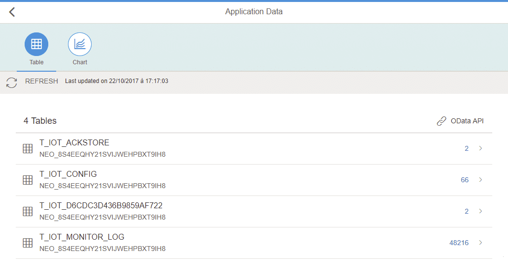
The table “T_IOT_D6CDC3D436B9859AF722” got created automatically as soon as a first message was received on the Data Endpoint. As you can see the last part of the table’s name corresponds to the Message Type ID.
The table “T_IOT_ACKSTORE” also gets created as soon as the Ack Endpoint receives its first message.
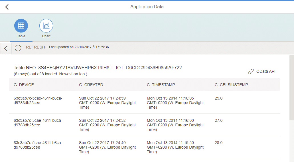
NOTE: We can see here that a time zone +2 is consider while on the chip not. There, the UTC/epoch time is used.
We now know that sending the message content as we shaped it, to the data endpoint reach the server properly. We thus need to see how we can do that from the Arduino board…
Sending data from the Arduino Board
Installing the Arduino IDE
Download an install the IDE from the Arduino website. There is also a web version available that will keep all your projects in a cloud and thus accessible from anywhere. At the time of my experiments I used the desktop version but it shouldn’t make any differences.
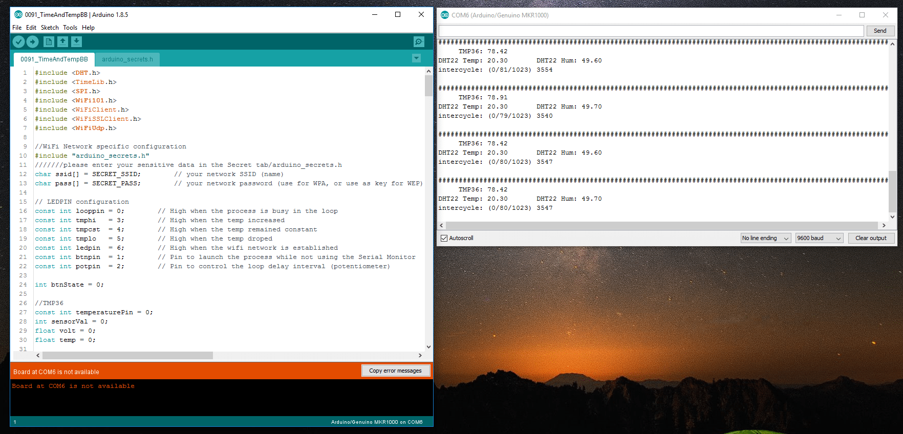
This screenshot shows on the left the edition area and on the right the serial monitor with can be used to troubleshoot your development. In most of the examples it is requested to start the serial monitor to initiate the process. That’s the “while (!Serial) {;}” instruction that you will see later in the code.
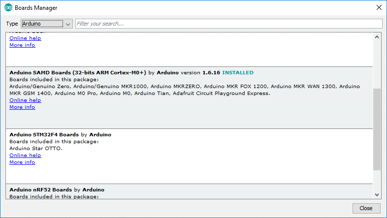
Installing the extra board
The MKR1000 board is not supported by the IDE out of the box the following board should be added through the Boards Manager in the Tools menu of the IDE.
- Arduino SAM Boards (32-bits ARM Cortex-M0+)
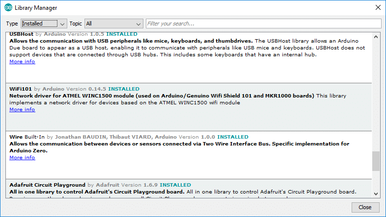
Installing additional libraries
While using specific sensor or some times more standard component such as the WiFi, libraries need to be added to the IDE and to project to work with them. The good news is that when you add a new library to the IDE you often get some sample projects along with it to guide or inspire you during your development.
Adding a library can be done through the Library Manager from the Sketch menu under Include Library. A lot of libraries can be just picked from the menu but in some cases you might need to download them from the Web and import them as well.
- WiFi101
- Time
Arduino MKR1000
The reasons why I choose this board amongst all the boards Arduino offers are two:
- It’s offered in a bundle. Since I have no background in electronic, having a standard set of components from the beginning is a preferred way to start.
- This board has a WiFi shield integrated out of the box.
Why Arduino rather than Raspberry Pi? I didn’t ask myself too many questions when I started this journey. I heard about Arduino, looked a bit what were the capabilities and just went for it.
If I have to highlight the difference between the two, Raspberry Pi is a full computer with a Linux OS and all the traditional connectivity features and Arduino is much lighter, probably less expensive and maybe more appropriate to projects with very little complexity. Why taking a bazooka to kill a fly?
Upgrade the WiFi Shield firmware
TIPS: The WiFi shield installed on the board supports:
- WEP with HEX key
- WAP TKIP
- WAP2 CCMP (AES-based)
As a start, run the script provided with the library to check the firmware and upgrade it if required. for more information on this operation, check the references mentioned at the end of this section.
Create the electronic circuit
Requirements
For those who would like to reproduce this exercise on their own, here is the bill of material with the prices at the time of writing this blog:
- Arduino MKR IoT Bundle (84,97€ including tax and shipment fees to Belgium from the Arduino Store)
- Arduino board MKR1000 (with headers mounted) (included in the kit)
- Temperature Sensor TMP36 (included in the kit) or even better the DHT22 (2,08 € from aliexpress) which can also measure the humidity. At the end of the day any sensor could do the trick: light, distance, … or even simpler the WiFi signal strength for which you wouldn’t even need anything else than the board itself.
- A couple of jump wires (included in the kit)
- A breadboard (included in the kit)
- Optionally, to have a visual indicator on the hardware side, to see where the process is busy (In our implementation, yellow indicates that we are in the setup method and Green in the loop excluding the ending delay)
- Two LEDs (included in the kit)
- Two Resistor 220 Ω (included in the kit)
Assembling the components together
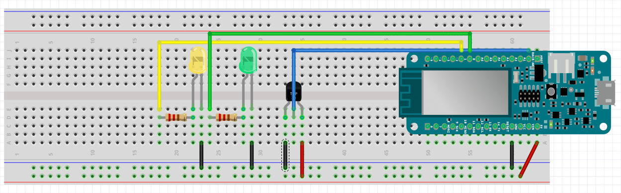
Here is a detailed close up of the Arduino board to see which pins are actually used.
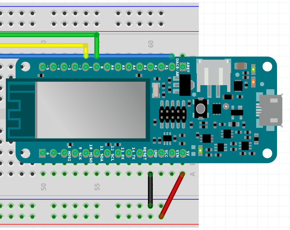
Schematic made using Fritzing. The board schematic itself can be downloaded from the Arduino web site itself.
IMPORTANT NOTE: While putting the TEMP36 temperature sensor on the breadboard if you look at it with the pins up right and the flat part above, the ground is on the third pin (starting to count from the left) and 5V on the first. If you put it the other way around as I did the sensor will heat a lot a produce a “nice” burning smell. You will have cooked it! Just in case.
Making the script
A couple of challenges along the road:
- Connecting the device to the WiFi is of course supported but not with all the security system/encryption type available. Here are some restrictions:
- WEP with HEX key is supported
- WEP with ASCII key is not supported
- WAP TKIP is supported
- WAP2 CCMP (AES-based) is supported
It is not easy to know what is supported and what is not. The easiest way to get it to work is to use tethering from your iPhone (which runs a supported WPA TKIP)…
- Finding the best way to deal with the NTP Server. Multiple implementations can be found on the net.
- Finding the right way to build the HTTP requests to send the data to SCP.
Complete the script
There is multiple ways to improve the script bellow such as establishing automatically a new connection to the WiFi when the connection get lost, make the time between two cycles adjustable using a potentiometer , using other technics to keep track of time, … The idea here is not to make a perfect script but rather to illustrate what can be done and how easily it can be done.
#include NOTE: Some of the methods above are just taken as they are from examples provided out of the box in the IDE or the libraries…
Running the script
As you might have seen from the script, the first couple of lines are dedicated to the initialization of the connections:
** Connection to the WiFi network in progress: . ** Connection established: IP Address: 172.20.10.11 ** Connecting to the NTP server: . ** Connecting to the SCP MMS Service ** Connection to SCP established ** Setup complete ! Here is a client request as it should be formed:
## BEGIN CLIENT REQUEST ################################ POST /com.sap.iotservices.mms/v1/api/http/data/63c3ab7c-5cae-4611-b6ca-d9783db25cee HTTP/1.1 Host: iotmmsi063866trial.hanatrial.ondemand.com:443 Content-Type:application/json;charset=utf-8 Authorization: Bearer 2b8358a867bdb7678b63c1973891b95 Content-Length: 110 {"mode":"sync","messageType":"d6cdc3d436b9859af722","messages":[{"timestamp":1508752380,"celsiusTemp":69.14}]} ## END CLIENT REQUEST ###################################The key data from this request are
- the data endpoint with the device ID
- the host where the sub-account can be found
- the security token
- the message type in the request body
- and finally the actual data that are sent
The reply to that request should be:
## BEGIN SERVER REPLY ################################# HTTP/1.1 200 OK Content-Type: application/json;charset=UTF-8 Transfer-Encoding: chunked Date: Mon, 23 Oct 2017 09:52:54 GMT Server: SAP Strict-Transport-Security: max-age=31536000; includeSubDomains; preload 52 {"msg":"1 message(s) received from device [63c3ab7c-5cae-4611-b6ca-d9783db25cee]"} 0 ## END SERVER REPLY ###################################References
- https://www.hackster.io/charifmahmoudi/arduino-mkr1000-getting-started-08bb4a
- https://www.arduino.cc/en/Guide/ArduinoWiFiShield101
- https://create.arduino.cc/projecthub/nekhbet/hello-world-with-arduino-genuino-mkr1000-relay-board-and-ap-81fb63
- Official API from Arduino web site of course
- All the demo scripts that are included in the IDE
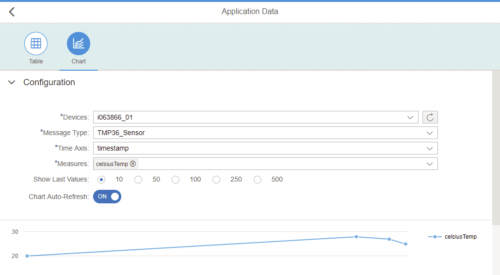
Monitoring the data coming into the SAP Cloud Platform
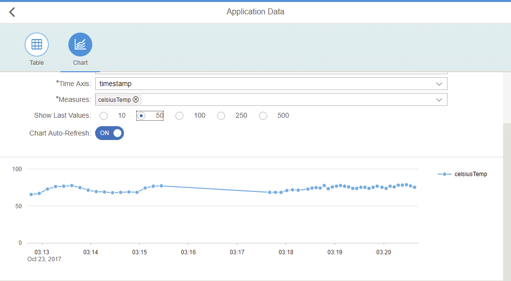
NOTE: As you can see the temperature values indicated on this chart are quite strange (between 50 and 100 C°) that’s because I put my sensor upside down the first time (mixing up anode and cathode) and thus cooked it… So the values are all wrong unfortunately but i